Study the Working Principle of the Circuit
Construct the simple light sensor circuit
On week 10th, (26/3/2018 - 1/4/2018)This week I try to construct the simple light sensor circuit to show the working principles of the sensor. However, this circuit does not show any results or outcome. In my view, there maybe some errors on my circuit connection.
Working Principles
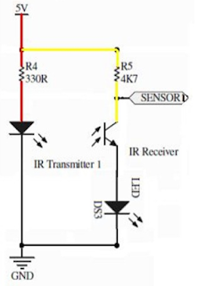
The IR Sensor Set consists of an IR transmitter and an IR receiver. With minimum interface and 5VDC
power, it can be used as a reflective type IR sensor for mobile robot or
low cost object detection sensor.
IR
Transmitter will always transmit IR light (Infrared), it is not visible
to human eyes. Since the transmitter and receiver is being arrange side
by side, theoretically, the receiver should not receive any or in most
cases, it will receive small amount of infrared emitted by the IR
transmitter. The working concept of IR receiver is similar to transistor
or LDR (Light Dependent Resistor). Just imagine this. Referring to
above diagram, the IR Receiver is like a transistor with the ‘base’
controlled by the IR light received. When there is no IR light receive,
the ‘collector’ of transistor does not allow current to sink to
’emitter’ further to ground of circuit. It is like very high resistance
from ‘collector’ to ’emitter’, blocking current going to ground. In this
case, the voltage at SENSOR1 node will be high, near to 5V.
When
the IR receiver receives more IR light, it changes the resistance at
‘collector’ and allow more current to sink to ground, and this is
similar to low resistance at the lower part of the circuit. So if you
know the voltage divider formula, I guess you understand what will
happen, the voltage at SENSOR1 will drop.
We
utilize this voltage changes to IR light to “know” whether there is
obstacle or not. Because when there is obstacle, IR light get reflected
to IR receiver further changes the voltage, monitoring the voltage
changes will get you an obstacle detection sensor.
